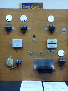
We were givin a honda multiplex board:
This is a picture of the board we used.The two white boxes in middle of the board is the nodes.the round white things are for the windows and their relays under them.The thing on the left at the bottom of board is the centralocking and it relays next to it.The big black thing at the bottom is the driver door node.This is what drivers use to open the windows and lock doors.The switch on top of it is the fault code switch and on the left of that one is the switch for the centralocking.
I used the wiring diagram above to identify the plugs and wire colours for communication lines between nodes:
MCU door=A15 to MCU (drivers) A2 is a brown wire.MCU (drivers) B1 to MCU(pasengers) B9 is a pink wire.
Earths and voltage supply lines between nodes:
Multiplex controll unit (door,drivers and pasenger)runs a pink wire from power to A1(door) A12(drivers) A24 (passengers)
We asked Scott to create a fault in the unit:
When this fault was created in this unit the drivers window was working but none of the other windows were working.The centralocking was also not working.This means that the comunication line to the units are not operating properly.Driver side was working because it does not go to nodes first it goes straight to window instead.
Next I had to use the wiring diagram to analyze the fault:
The comminucation lines are not connecting with the nodes so the nodes do not work.This could be because there is a break in the line.
I had to put the system in test mode.I did this and it came up with one short beep.The fault that comes up is the same as what I diagnosed it with before.
We cant do a continuity test because you can break it if you induse current into it when trying to test it.Therefore you are never aloud to use a test light on this circuit because it has almost no current in it.
We tested voltage for brown wire to unit and got a voltage of 0.2v so there is a high resistance so it is an open circuit.voltage with groun is stil 8.5v because they are still comunicatting.Pink wire was good.voltage flowing both ways so I got 8.3v on both sides with a 0.2v drop in the middle.
The door unit has no inputs to the drivers window because there is a break in the comunication line to drivers side.Has beep at the interior light so it is working.Unit not sending input to the nodes.
To diagnose I have to do a voltage drop test between A15 and A2.I did this and got a result of 8.7v at A15 and 8.5 at A2 so there is a voltage drop of 0.2v.this shows high resistance.
We were asked to put the system into sleap mode.We could not do this because the board we used was not wired up to do so yet.Sleap mode is used so the system does not flaten the batery when you turn the ignition of.


No comments:
Post a Comment